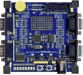
There are currently four FreeRTOS ports for the Philips LPC2000 ARM7 based embedded microcontroller. This page relates only to the port for the IAR development tools. The port was developed on an MCB2100 development/prototyping board using a J-LINK USB JTAG interface (instructions are provided should you wish to use an alternative development board). The MCB2100 is a fully featured and comprehensive prototyping board that allows easy access to the LPC2129 peripherals and includes 8 built in LEDs which are utilised by the FreeRTOS demo application. Note: If this project fails to build then it is likely the version of IAR Embedded Workbench being used is too old. If this is the case, then it is also likely that the project file has been (silently) corrupted and will need to be restored to its original state before it can be built even with an updated IAR version.
IMPORTANT! Notes on using the IAR LPC2000 RTOS portPlease read all the following points before using this RTOS port.See also the FAQ My application does not run, what could be wrong? Source Code OrganisationThe FreeRTOS download contains the source code for all the FreeRTOS ports, so contains more files than used by this demo. See the Source Code Organization section for a description of the downloaded files and information on creating a new project.The IAR Embedded Workbench project file for this demo can be found in the Demo/ARM7_LPC2129_IAR directory, which also contains main.c, the source file containing the main() function.
The Demo/ARM7_LPC2129_IAR/SrcIAR and the Demo/ARM7_LPC2129_IAR/resource directories
contain support files for the IAR Philips build environment.
The Demo ApplicationThe FreeRTOS source code download includes a fully preemptive multitasking demo application for the IAR LPC2129 RTOS port.FunctionalityThe demo applications can be built using the IAR development tools KickStart version - which has a file size limit of 32K bytes.Two configurations are provided within the project file - 'flash debug' with no optimisation, and 'flash bin' will full optimisation (barring the static clustering option). The demo application creates 25 of the standard demo tasks, the idle task, and a 'Check' task. See the demo application section for details of the individual tasks. When executing correctly the demo application will behave as follows:
Demo application hardware setupThe demo application includes tasks that send and receive characters over the serial port. The characters sent by one task need to be received by another - if any character is missed or received out of sequence an error condition is flagged. A loopback connector is required on the serial port for this mechanism to operate (simply connect pins 2 and 3 together on the P2 serial port connector of COM 0).The demo application uses the LEDs built into the prototyping board so no other hardware setup is required. Building the demo applicationSimply open the RTOSDemo.ewp project workspace file from within the IAR IDE, select the required configuration, then select 'Make' from the IDE 'Project' menu. The application should build with no errors or warnings.
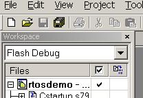 Selecting the 'Flash Debug' configuration Running the demo applicationThe IAR port cannot be executed using the IAR simulator so must be executed on the target hardware:
An alternative JTAG interface can be selected using the Debugger category within the project options dialogue box.
Configuration and Usage DetailsRTOS port specific configurationConfiguration items specific to this port are contained in Demo/ARM7_LPC2129_IAR/FreeRTOSConfig.h. The constants defined in this file can be edited to suit your application. In particular - the definition configTICK_RATE_HZ is used to set the frequency of the RTOS tick. The supplied value of 1000Hz is useful for testing the RTOS kernel functionality but is faster than most applications require. Lowering this value will improve efficiency.Each port #defines 'BaseType_t' to equal the most efficient data type for that processor. This port defines BaseType_t to be of type long. Note that vPortEndScheduler() has not been implemented. Interrupt service routinesAn interrupt service routine that does not cause a context switch has no special requirements and can be written as per the normal IAR syntax. For example:
    static __arm __irq void vAnISR( void )
    {
        /* ISR C code goes here. */

        /* End the interrupt in the VIC. */
        VICVectAddr = 0;
    }
Often you will require an interrupt service routine to cause a context switch. For example a serial port character being received may wake a high priority task that was blocked waiting for the character. If the ISR interrupted a lower priority task then it should return immediately to the woken task. Limitations in the IAR inline assembler necessitate such interrupt service routines include an assembly file wrapper.
An example of an ISR with context switching capabilitiesThe main body of the ISR can be written in C within any source file as per the following template. This is just a normal ARM mode function that includes a call to portEND_SWITCHING_ISR() at its end.
    /* For simplicity the C function should operate in ARM mode.
       Note that the __irq modifier is NOT used. */

    __arm void vASwitchingISR( void )
    {
        char cContextSwitchRequired;

        /* Write the ISR body here as per normal.

        A boolean is used to say whether a context switch is required.
        In this example assume we posted onto a queue and this caused a
        task to be woken. */

        cContextSwitchRequired = pdTRUE;

        /* Immediately before the end of the ISR call the
        portEND_SWITCHING_ISR() macro. */

        portEND_SWITCHING_ISR( ( cContextSwitchRequired ) );

        /* End the interrupt in the VIC. */
        VICVectAddr = 0;
    }
See the function vSerialISR() defined in Demo/ARM7_LPC2129_IAR/serial/serial.c for a complete example.
The entry point for the ISR has to be written in an assembly file. This just places a call to the C function between
calls to the portSAVE_CONTEXT() and portRESTORE_CONTEXT() macros respectively as per the following template:
To use a part other than an LPC2129The LPC2129 uses a standard ARM7 core with processor specific peripherals. The core real time kernel components should be portable across all ARM7 devices - but the peripheral setup and memory requirements will require consideration. Items to consider:
Switching between the pre-emptive and co-operative RTOS kernelsSet the definition configUSE_PREEMPTION within Demo/ARM7_LPC2129_IAR/FreeRTOSConfig.h to 1 to use pre-emption or 0 to use co-operative.Compiler optionsAs with all the ports, it is essential that the correct compiler options are used. The best way to ensure this is to base your application on the provided demo application project file - as described in the Source Organization section.Execution ContextThe RTOS scheduler executes in supervisor mode, tasks execute in system mode.
NOTE! : The processor MUST be in supervisor mode when the RTOS scheduler is started (vTaskStartScheduler is called). The demo applications included in the FreeRTOS download switch to supervisor mode prior to main being called. If you are not using one of these demo application projects then ensure Supervisor mode is entered before calling vTaskStartScheduler(). Interrupt service routines always run in ARM mode. All other code will run in either ARM or THUMB mode depending on the build. It should be noted that some of the macros defined in portmacro.h can only be called from ARM mode code, and use from THUMB code will result in a compile time error. The Embedded Workbench project is configured for THUMB mode - see the LPC2006 GCC port for an example of the configuration required to use just ARM mode. Demo/ARM7_LPC2129_IAR/Startup.s configures stacks for system/user, IRQ and SWI modes only. SWI instructions are used by the real time kernel and can therefore not be used by the application code. Memory allocationSource/Portable/MemMang/heap_2.c is included in the ARM7 demo application makefile to provide the memory allocation required by the real time kernel. Please refer to the Memory Management section of the API documentation for full information.Serial port driverIt should also be noted that the serial drivers are written to test some of the real time kernel features - and they are not intended to represent an optimised solution.
Copyright (C) Amazon Web Services, Inc. or its affiliates. All rights reserved.
|
|||||||||||||||||||